- 您现在的位置:买卖IC网 > Sheet目录17370 > V048F480T006-CB (Vicor Corporation)VTM CURRENT MULTIPLIER EVAL BOAR
�� �
�
�Not� Recommended� for� New� Designs� -� Replaced� by� VTM48Ex480y006A00�
�Application� Note�
�V048F480T006�
�Parallel� Operation�
�In� applications� requiring� higher� current� or� redundancy,� VTM� current�
�multipliers� can� be� operated� in� parallel� without� adding� control� circuitry�
�or� signal� lines.� To� maximize� current� sharing� accuracy,� it� is� imperative�
�that� the� source� and� load� impedance� on� each� VTM� module� in� a� parallel�
�array� be� equal.� If� the� modules� are� being� fed� by� an� upstream� PRM� ?�
�regulator,� the� VC� nodes� of� all� VTM� modules� must� be� connected� to� the�
�PRM� module� VC.�
�To� achieve� matched� impedances,� dedicated� power� planes� within� the� PC�
�Input� Impedance� Recommendations�
�To� take� full� advantage� of� the� current� multiplier’s� capabilities,� the�
�impedance� of� the� source� (input� source� plus� the� PC� board� impedance)�
�must� be� low� over� a� range� from� DC� to� 5� MHz.� Input� bypass� capacitance�
�may� be� added� to� improve� transient� performance� or� compensate� for�
�high� source� impedance.� The� VTM� module� has� extremely� wide�
�bandwidth� so� the� source� response� to� transients� is� usually� the� limiting�
�factor� in� overall� output� response� of� the� module.�
�Anomalies� in� the� response� of� the� source� will� appear� at� the� output� of�
�board� should� be� used� for� the� output� and� output� return� paths� to� the�
�the� VTM� module,� multiplied� by� its� K� factor� of� 1�
�.� The� DC� resistance�
�array� of� paralleled� VTMs.� This� technique� is� preferable� to� using� traces� of�
�varying� size� and� length.�
�The� VTM� module� power� train� and� control� architecture� allow�
�bi-directional� power� transfer� when� the� module� is� operating� within� its�
�specified� ranges.� Bi-directional� power� processing� improves� transient�
�response� in� the� event� of� an� output� load� dump.� The� module� may�
�operate� in� reverse,� returning� output� power� back� to� the� input� source.� It�
�does� so� efficiently.�
�Thermal� Considerations�
�VI� Chip� ?� products� are� multi-chip� modules� whose� temperature�
�distribution� varies� greatly� for� each� part� number� as� well� as� with� the�
�input� /output� conditions,� thermal� management� and� environmental�
�conditions.� Maintaining� the� top� of� the� V048F480T006� case� to� less� than�
�100°C� will� keep� all� junctions� within� the� VI� Chip� module� below�
�125°C� for� most� applications.� The� percent� of� total� heat� dissipated�
�through� the� top� surface� versus� through� the� J-lead� is� entirely� dependent�
�on� the� particular� mechanical� and� thermal� environment.� The� heat�
�dissipated� through� the� top� surface� is� typically� 60%.� The� heat� dissipated�
�through� the� J-lead� onto� the� PCB� board� surface� is� typically� 40%.� Use�
�100%� top� surface� dissipation� when� designing� for� a� conservative�
�cooling� solution.�
�It� is� not� recommended� to� use� a� VI� Chip� module� for� an� extended� period�
�of� time� at� full� load� without� proper� heat� sinking.�
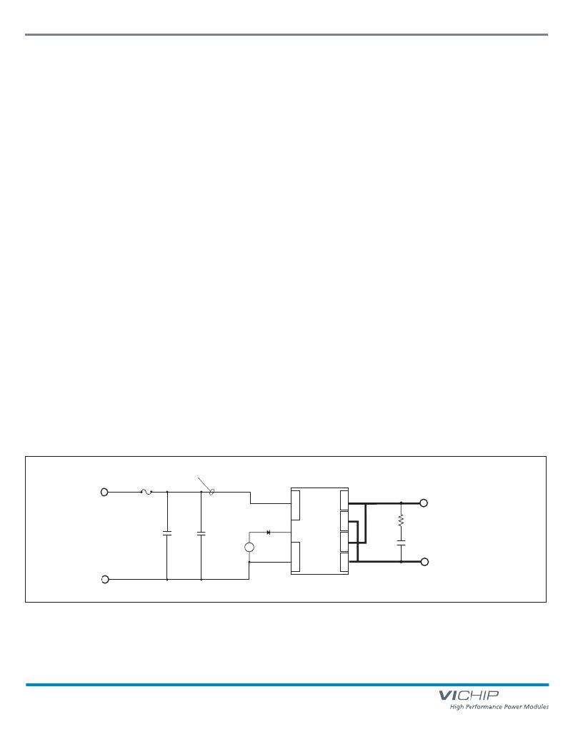
�Input� reflected� ripple�
�measurement� point�
�F1�
�of� the� source� should� be� kept� as� low� as� possible� to� minimize� voltage�
�deviations� on� the� input� to� the� module.� If� the� module� is� going� to� be�
�operating� close� to� the� high� limit� of� its� input� range,� make� sure� input�
�voltage� deviations� will� not� trigger� the� input� overvoltage� turn-off�
�threshold.�
�Input� Fuse� Recommendations�
�VI� Chip� products� are� not� internally� fused� in� order� to� provide� flexibility� in�
�configuring� power� systems.� However,� input� line� fusing� of� VI� Chip�
�modules� must� always� be� incorporated� within� the� power� system.� A� fast�
�acting� fuse� is� required� to� meet� safety� agency� Conditions� of�
�Acceptability.� The� input� line� fuse� should� be� placed� in� series� with�
�the� +In� port.�
�10A�
�Fuse�
�+In�
�+Out�
�-Out�
�R3�
�5� m� Ω�
�+�
�Ro�
�C1�
�47� μF�
�Al� electrolytic�
�C2�
�0.47� μF�
�ceramic�
�14� V� +–�
�TM�
�VC�
�PC�
�-In�
�VTM� ?�
�+Out�
�K�
�-Out�
�C3�
�9.4� μF�
�Load�
�–�
�Notes:�
�C3� should� be� placed� close�
�to� the� load�
�R3� may� be� ESR� of� C3� or� a�
�separate� damping� resistor.�
�Figure� 15� —� VTM� module� test� circuit�
�VTM� ?� Current� Multiplier�
�Page� 9� of� 11�
�Rev� 3.1�
�01/2014�
�vicorpower.com�
�800� 927.9474�
�发布紧急采购,3分钟左右您将得到回复。
相关PDF资料
EBA10DRSN-S288
CONN EDGECARD 20POS .125 EXTEND
EBA10DRSD-S288
CONN EDGECARD 20POS .125 EXTEND
LQH55PN2R2NR0L
INDUCTOR POWER 2.2UH 2500MA 2220
EBM06DRSI-S288
CONN EDGECARD 12POS .156 EXTEND
RBM08DSUN
CONN EDGECARD 16POS DIP .156 SLD
V048F320T009-CB
VTM CURRENT MULTIPLIER EVAL BOAR
RO-1505S/H
CONV DC/DC 1W 15VIN 05VOUT
RM-243.3S/H
CONV DC/DC 0.25W 24VIN 3.3VOUT
相关代理商/技术参数
V048F480T009
制造商:POWERBOX 制造商全称:Powerbox 功能描述:300W DC/DC VOLTAGE TRANSFORMATION MODULE PRELIMINARY
V048F480T012
制造商:POWERBOX 制造商全称:Powerbox 功能描述:300W DC/DC VOLTAGE TRANSFORMATION MODULE PRELIMINARY
V048F480T015
制造商:POWERBOX 制造商全称:Powerbox 功能描述:300W DC/DC VOLTAGE TRANSFORMATION MODULE PRELIMINARY
V048F480T025
制造商:POWERBOX 制造商全称:Powerbox 功能描述:300W DC/DC VOLTAGE TRANSFORMATION MODULE PRELIMINARY
V048F480T030
制造商:POWERBOX 制造商全称:Powerbox 功能描述:300W DC/DC VOLTAGE TRANSFORMATION MODULE PRELIMINARY
V048F480T040
制造商:POWERBOX 制造商全称:Powerbox 功能描述:300W DC/DC VOLTAGE TRANSFORMATION MODULE PRELIMINARY
V048F480T050
制造商:POWERBOX 制造商全称:Powerbox 功能描述:300W DC/DC VOLTAGE TRANSFORMATION MODULE PRELIMINARY
V048F480T060
制造商:POWERBOX 制造商全称:Powerbox 功能描述:300W DC/DC VOLTAGE TRANSFORMATION MODULE PRELIMINARY